1. Welcome to Explorer!
Thank you for downloading Software Synthesizer - Explorer.
Explorer does not have a wavetable engine or effects, but it has features such as a
waveshaper, phase ring modulation, a powerful unison function that can be set for each oscillator, and a group of modulators that can access almost all parameters. It has a function that does not exist.
Each module is also designed according to exemplary algorithms. With a textbook in hand, you should be able to meet the needs of those who want to learn synthesizers from now on.
A small number of presets are also available.
Have fun with it.
Fabric 70 - Ken Ito
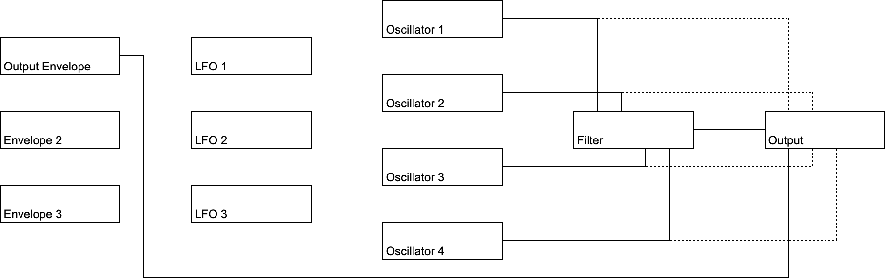
2. Flow
Explorer consists of Envelope x 3, LFO x 3,
Oscillator x 4, Filter x 1, Output x 1.
Oscillators 1 - 4 generate audio signals at note-on triggers.
The generated signal is output as an actual sound wave through Filter and Output.
By default, Oscillators 1-4 are connected to the Filter, but they can also be routed directly to the Output, as indicated by the dotted line.
Output Envelope, Envelope 2, 3, LFO 1-3 are not for the audio signal itself, but for controlling parameters of other modules over time, such as Oscillators 1-4 and Filter. These can be freely connected to any module.
3. Setup
Download Explorer from this website.
http://fabric70.com/explorer.html
Mac
Audio Units, please
move or copy Explorer.component to the following path.
~/Library/Audio/Plug-Ins/Components/
When using as VST3, move or copy Explorer.vst3 to the following path.
~/Library/Audio/Plug-Ins/VST3/
Windows
Explorer.vst3 to the following path.
C:\Program Files\Common Files\VST3.Presets
are available. If you want to use it, move and copy Presets/Fabric 70/Explorer (VST3 Presets/Fabric 70/Explorer for Windows) included in the download folder to any directory.
You are now ready to go. Then start your DAW and insert Explorer on your instrument track.
4. Reference
Explore’s Section = Explains the functions installed in each module.
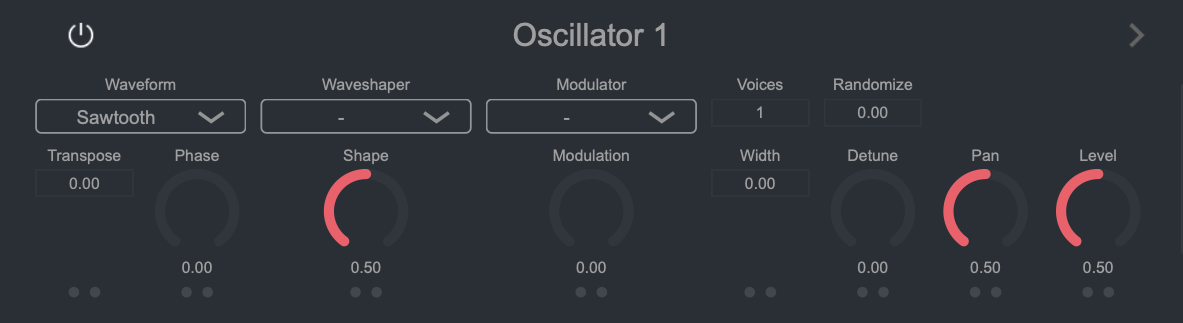
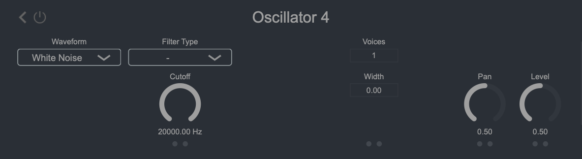
4.1.Oscillators
This section is the sound source.
The Explorer features 4 oscillators.
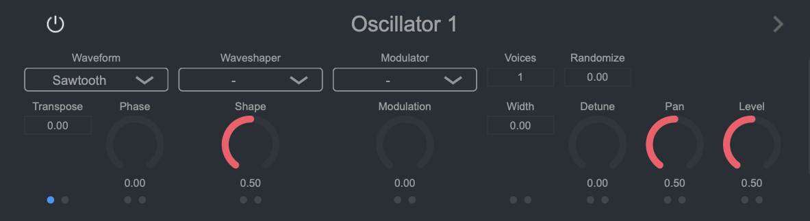
4.1.1. Parameter
Power
is the power supply. Doesn't work when off.
Waveform
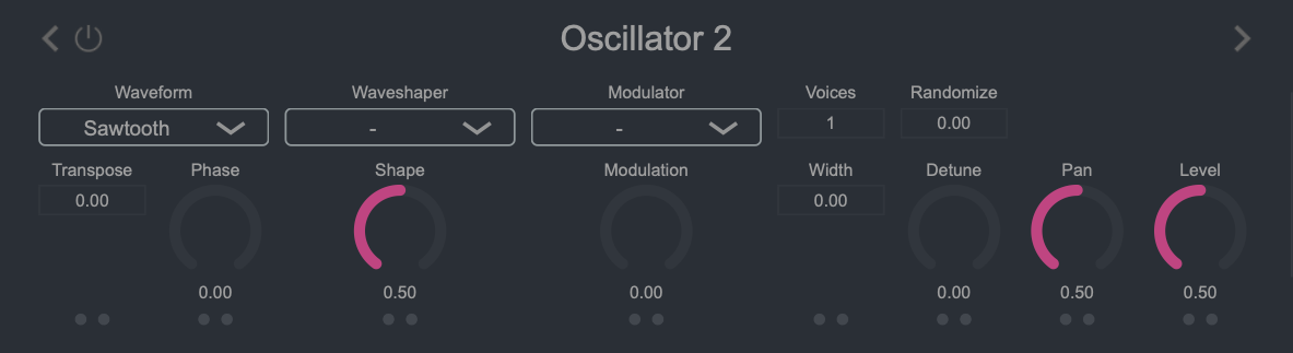
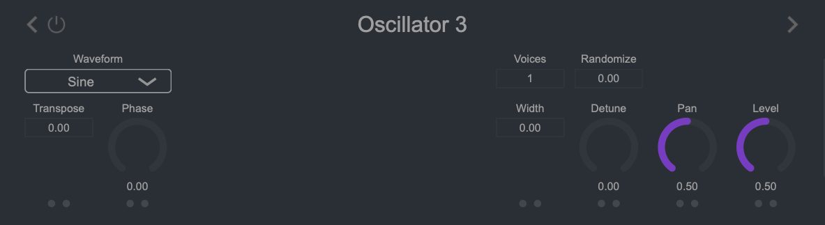
Oscillator 1-3 are common.
You can choose from the following four types.
.
Also called sine waveA waveform without overtones.
Triangle
Square, this waveform contains odd-order harmonics, but the amount is small.
Sawtooth
is the most frequently used waveform in subtractive synthesis like this software, as it contains all overtones.
Square
A waveform containing odd harmonics. By using Waveshaper - Phase Distortion, you can change the duty ratio.
Oscillator 4 is dedicated to noise output, and
you can choose from two types:
White Noise
A noise wave containing all frequency components equally.
Pink Noise
frequency, with higher frequency sounds becoming weaker.
Transpose
oscillator. ±1 is a semitone, ±12 is an octave.
Phase
audio signal.
Waveshaper
Settings for the wave shaping feature that changes the shape of the audio signal.
There are four Waveforms, but you can create a variety of sounds by using the oscillator modulation described in this section and the next section.
You can choose from the following five types.
Basic Applies
a curvilinear shape change in the opposite direction to the left and right from the center of the audio signal per cycle.
Synchronize Synchronize
is commonly called oscillator sync.
Originally, by synchronizing the frequency of one oscillator to another, the basic waveform was distorted, resulting in a strong timbre change. You can get that effect with just an oscillator.
Phase Distortion Adds
shape change by changing the angle between two phase points.
Stretch Reduces
the phase angle required to generate a one-cycle waveform. It does not generate an audio signal for phase angles that are too small. Therefore, it gives shape change as if the waveform expands and contracts.
flip
threshold, it gives a shape change like a notch.
Shape
shape change.
Modulator
Oscillator modulation function setting that uses audio signals output from other oscillators = addition and multiplication.
You can choose from the following two types.
PM means Phase Modulation, RM means Ring Modulation.
PM Oscillator n-
phase modulation.
Adds an audio signal generated by another oscillator to the phase angle before the audio signal is generated, giving a modulation effect.
RM Oscillator n
Ring modulation.
Multiplies the audio signal by an audio signal generated by another oscillator to create a modulation effect.
Modulation
Controls the effect of modulation.
Voices
note-ons.
By using it together with Width and Detune (described later), you can add breadth and thickness to the sound.
For example, if Oscillator 1 is Voices: 2 and Oscillator 2 is Voices: 4, and you press the key with note number: C3, 2 Oscillator 1 and 4 Oscillator 2 will sound C3.
Randomize
Controls the range over which the starting angle of the audio signal is randomized.
If the starting angles of the audio signals pronounced by Voices are aligned, the
volume will only increase, and the desired effect will not be obtained.
Also, unison with only Detune, without using this parameter, will create depth due to the different pitches of multiple audio signals, but it will produce a large undulation immediately after the sound. Again, this is because the waveform start angles are aligned. This function is an effective means of avoiding these.
WidthControls
the stereo width of the audio signal.
This parameter also has no effect if the start positions of multiple sounded waveforms are aligned. It is a prerequisite function to use with Randomize.
Detune
Controls the amount of pitch deviation for each multi-sounded audio signal. The deviation amount when this parameter is the maximum value follows the Range setting in the previous section.
Pan
sound.
0.5 for center, 0 for left channel only, 1 for right channel only.
Level
the oscillatorControls the output level of
The output level of the final audio signal is handled by the Output section, so the role of this function is to adjust the output level relative to other oscillators.
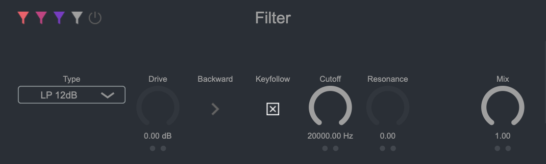
4.2.Filter This
section cuts unnecessary bands from the audio signal generated by the Oscillator, or increases or decreases specific bands to create the desired sound.
4.2.1. Parameter
Power
is the power supply. Doesn't work when off.
Oscillator n > Filter
You can choose whether or not to pass through the filter section for each oscillator.
Audio signals from oscillators that are turned off will skip this section and be sent directly to the Output section.
Filter Type
You can choose from the following types.
LP 12dB
LP 24dB
low pass filter.
Attenuates signal components above the cutoff frequency.
BP 12dB
PB 24dB
band pass filter.
Allows signal components in the band around the cutoff frequency to pass, and attenuates signal components above and below this frequency band.
HP 12dB
HP 24dB
high pass filter.
Attenuates signal components below the cutoff frequency.
Notch 12dB
Notch 24dB
notch filter.
Attenuates a narrow band around the resonant frequency. Minimize the impact on the rest of the signal.
Peak 12dB
peak filter.
Amplifies a narrow band around the resonant frequency. Minimize the impact on the rest of the signal.
Allpass 12dB
allpass filter.
Only changes the phase near the cutoff frequency of the input signal.
Low Shelf Boosts or attenuates frequencies below the 12dB
cutoff frequency by the specified amount.
High Shelf Amplifies or attenuates frequencies above the 12dB
cutoff frequency by the specified amount.
Comb +
Comb -
is a comb filter.
Mixes the original signal with one or more copies of the delayed signal.
At some frequencies these signals combine to cause phase cancellation, and at others they produce enhancement. This results in a sharp frequency spectrum with multiple resonant peaks.
Comb+ uses positive feedback on the delay line. Comb-, on the other hand, uses negative feedback.
Drive
Controls the level of the
This section has a soft clip function, and by amplifying the audio signal, you can obtain a natural distortion effect.
backward softclipping
processes are performed.
Off : Soft Clip -> Filter -> Output section
On : Filter -> Soft Clip -> Output section
When Drive is applied, turn it on when you want stronger distortion.
When Keyfollow
is turned on, Cutoff will follow the note number.
Cutoff Cutoff
frequency control.
Controls the delay time when Comb +, Comb - is selected.
Resonance
Controls the level of the bands around the
Controls the width of the affected band when Notch, Peak, or Allpass is selected, and the amount of feedback when Comb is selected.
Gain
Controls the level of specific bands.
Used for Peak, Low Shelf, and High Shelf.
Amplifies or attenuates the band near Peak >> Cutoff.
Low Shelf … Amplifies and attenuates the band lower than Cutoff.
High Shelf … Amplifies and attenuates the band higher than Cutoff.
Peak amplifies or attenuates the band near the Cutoff, Low Shelf the band below the Cutoff, and High Shelf the band above the Cutoff.
Mix
Controls the mix ratio between the filtered signal and the original signal.
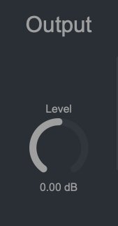
4.3.Output
This section controls the level of the audio signal.
4.3.1. Parameter
Level
Controls the level of the output audio signal.
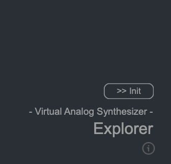
4.4.Information In
addition to displaying version information, this section is responsible for initialization.
4.4.1. Parameter
Init
the settings of this softwareInitialize
Information
the version of this software.
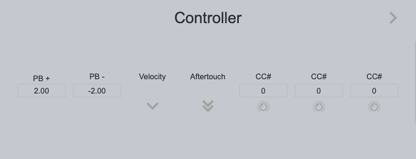
4.5.Controller
This section determines the behavior when MIDI information such as pitch bend, velocity and control change is received.
4.5.1. Parameter
PB +
This is the maximum pitch value that changes when the bender is moved upward.
PB -
The maximum pitch change when moving the bender down.
Velocity
is on, velocity modulation is enabled.
Aftertouch
is on, aftertouch modulation is enabled.
CC#
control change, specify the control number with this parameter.
Control Change
is on, modulation by control change from the control number set by CC# is enabled.
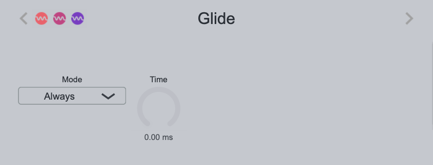
4.6.Glide
This section deals with the glide function, one of the MIDI control changes.
4.6.1.Parameters
Oscillator 1 > Glide
Oscillator 2 > Glide
Oscillator 3 > Glide
Determines whether glide is enabled for each oscillator.
Mode
You can choose from two types of glide modes.
With Always, there is always a glide effect, and with Legato, the glide effect occurs only when the note-on continues.
4.7.Voicing
This is the section to change to monophonic mode, set the number of voices, and set the overall pitch.
4.7.1. When parameter
Monophonic
is on, Sensuou operates as a monophonic synthesizer.
Legato
Monophonic is on. With this setting enabled, if another note-on occurs during note-on, retrigger such as Envelope or LFO reset will not be performed.
Controls
the maximum number of voices that can be pronounced simultaneously.
Transpose
oscillator. ±1 is a semitone, ±12 is an octave.
Range Of Detune
Controls the range of pitch deviation when Detune is at maximum.
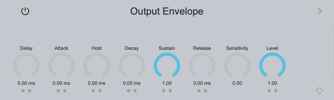
4.8.Envelopes
regular changes to
parameters over time from note-on.
Since the Output Envelope is directly connected to the Output section, the output volume follows the Output Envelope setting.
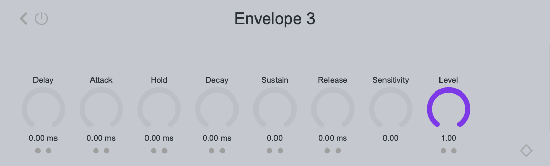
4.8.1. Parameter
Power
is the power supply. Doesn't work when off.
Delay
Controls the time from note-on until the envelope starts.
Attack
envelope to start and reach its maximum level.
Hold
Delay andControls the amount of time that the maximum level is maintained before transitioning to Decay via
Decay
Controls how long it takes to reach Sustain from maximum
Sustain
during note-on after going throughControls the level maintained
release
note off until the level reaches zero.
Sensitivity
Applies velocity to the output level of the
Level
Controls the output level of the envelope.
Envelope Shapers
Attack, Decay, and Release control how much the envelope increases or decreases over time. At 0%, it is linear, but you can give a curvilinear time change that swells inward as the ratio goes to + and outward as it goes to -.
4.9.LFOsThis section applies
low-frequency signals to the parameters in a regular manner.
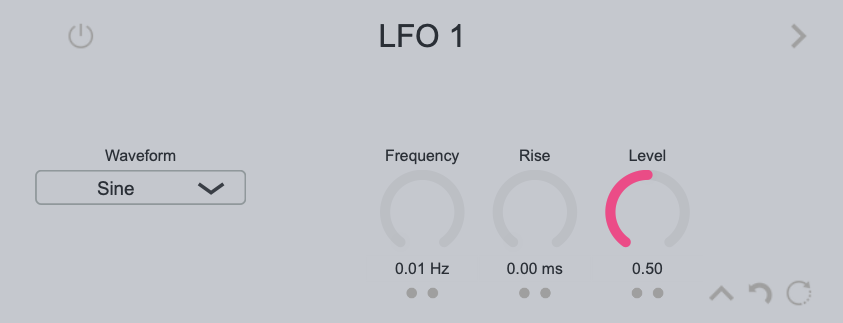
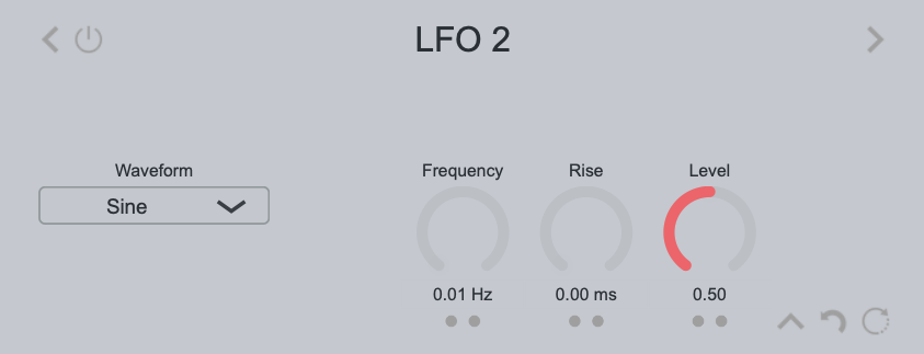
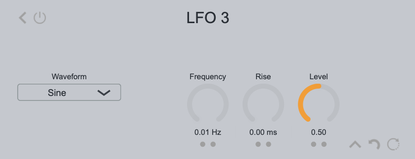
4.9.1 Parameter
Power Power
supply. Doesn't work when off.
Waveform Type
7 types belowYou can select from
Sine
is a sine wave.
Triangle A
triangle wave.
Trapezoid
A trapezoidal waveform.
Ramp Up
A linear waveform that rises to the right.
Ramp Down
This is a linear waveform that descends to the right.
Pulse
Pulse wave. You can vary the ratio by using Pulsewidth.
Random
Outputs a random value every cycle.
Pulsewidth Controls
the width when Pulse is selected from Waveform Type.
Frequency
Controls the frequency of the LFO. When Synchronize (described later) is on, the cycle is controlled by the ratio to the DAW BPM.
Rise
note-on until the LFO reaches its maximum amplitude.
Level
Controls the output level of the oscillator.
Reset Point
note-on.
This is valid when Reset (described later) is on.
Amplitude Type
the amplitude range of the LFO from the
You can choose
-1 to 1
LFO amplitude is positive or negative.
0 to 1
LFO amplitude is positive only.
Reset
is on, resets the LFO signal phase angle at note-on.
Synchronize
is on, you can specify the percentage of DAW BPM from Frequency.
5. Let's modulate
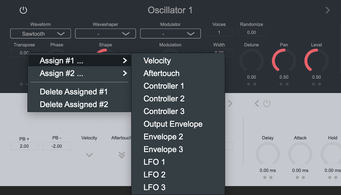
Here, we will explain how to assign the modulators of Velocity, Aftertouch, CC#, Envelope, and LFO to parameters >> Modulate.
The Explorer is equipped with 11 modulators below.
Velocity
Aftertouch
Controller 1
Controller 2
Controller 3
Output Envelope
Envelope 2
Envelope 3
LFO 1
LFO 2
LFO
these modulators to parameters,
you can give changes over time.
The steps are easy. After moving the mouse pointer to the parameter you want to assign, right-click to display the popup menu.
parameter in Explorer
You can assign up to two modulators to one
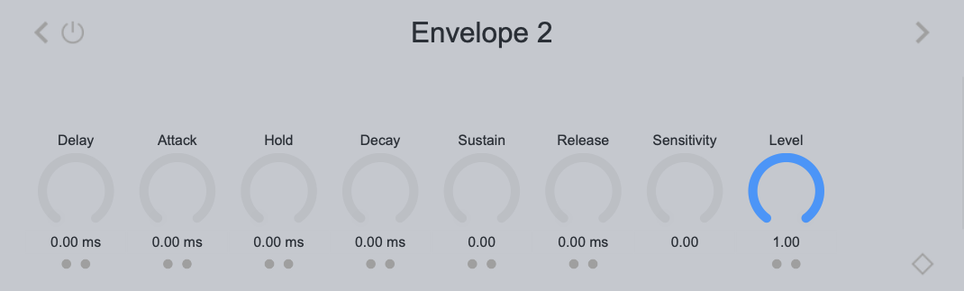
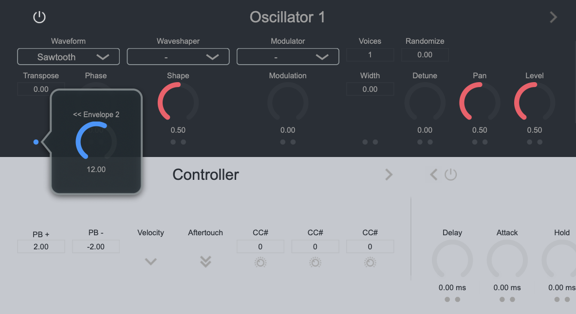
As a practice, use Oscillator 1's Transpose to open the popup menu and select Envelope 2 from Assign #1.
The LED at the bottom of Transpose glowed blue. This indicates that Envelope 2 has been assigned.
Next, click this LED to display a slider that adjusts the amount of modulation. Let's change it to 12. Modulation from Envelope 2 will now add up to an octave.
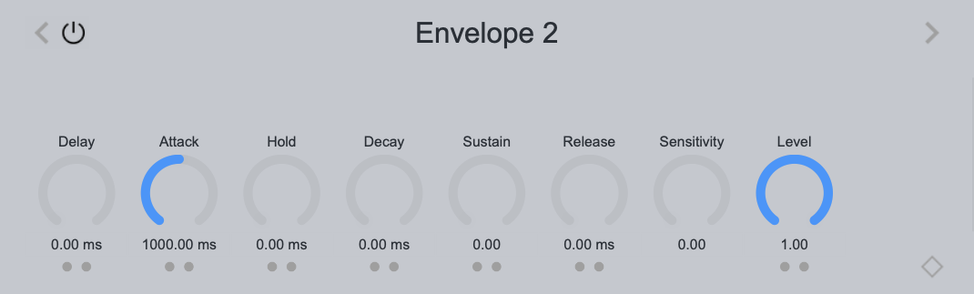
The last setting is Envelope 2, which is the modulation source.
After turning on Power, set Attack to 1000ms. With this, the Transpose of Oscillator 1 should rise by one octave over a period of one second at the note-on trigger.